Thursday, January 26, 2017

1. Compare the calculated and measured equivalent resistance values between the nodes A and B for three circuit configurations given below. Choose your own resistors. (Table)


RESISTOR
RESISTOR VALUE (Ω)
R1
100
R2
47
R3
100
R4
120


2. Apply 5V on a 120 Ω resistor. Measure the current by putting the multimeter in series and parallel. Why are they different?

With 5 V applied to a resistor in series with the multimeter, the current was measures to be 40.8 Ma, which is in accordance with ohm’s law, whereby the voltage divided by the resistance is equal to the current (5 V /120 Ω = 41.7 mA). With the multimeter connected in series, however, the current was measured to be 0 A because the resistor was shorted by the multimeter, meaning current did not flow through it.

3. Apply 5 V to two resistors (47 Ω and 120 Ω) that are in series. Compare the measured and calculated values of voltage and current values on each resistor.


Measured Value
Calculated Value
120 Ω
voltage
3.60 V
3.59 V
current
29.7 mA
29.9 mA
47 Ω
Voltage
1.42 V
1.41 V
Current
29.8 mA
29.9 mA

Calculated values and measure values for both resistance and Voltage across each resistor in this circuit tended to math to within 1%

4. Apply 5 V to two resistors (47 Ω and 120 Ω) that are in parallel. Compare the measured and calculated values of voltage and current values on each resistor.


Measured Value
Calculated Value
120 Ω
voltage
5.03 V
5.00 V
current
40.7 mA
41.7 mA
47 Ω
Voltage
5.03 V
5.00 V
Current
127 mA
148 mA


These measurements were less consistent with the theoretical values than for the same components connected in parallel. There are many possible reasons for this. For instance, wires could have had a resistance value that was not negligible as the calculations assume. It is also possible that components came in contact that shouldn’t have, thus limiting the accuracy of the reading. 

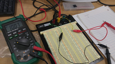
5. Compare the calculated and measured values of the following current and voltage for the circuit below: (breadboard photo)

a. Current on 2 kΩ resistor,
Picture 1: Current going through the 2k resistor

The measured current value for the 2k resistor was 2.06 mA and the measured value for the current was 2.5 mA.

b. Voltage across both 1.2 kΩ resistors.


Picture 2: Voltage going through the 1.2k Resistor at the node with the 2k Resistor


Picture 3: Voltage going through the 1.2k Resistor in the middle of the circuit


The 1.2k Resistor connected to the 2k and 100 ohm node has a measured voltage value of .85 volts and a calculated voltage value of .78 volts. The 1.2k resistor in the middle of the circuit has a measured voltage of .717 volts and a calculated value of .733 volts. The lower voltage makes sense because there is more resistance before the voltage meets the second 1.2k resistor. 

6. What would be the equivalent resistance value of the circuit above (between the power supply nodes)?


Equivalent resistance: 2520 Ω 

By taking observing that the 1k and 1.2 k Ω resistors in the upper right hand corner of the above figure are in parallel, their equivalent resistance can be calculated to be 545.5 Ω. This equivalent resistance is in series with the 100 Ω resistor in the upper left hand corner, and the combined resistance is found through simple addition to be 645.5 Ω. This is in parallel with the second 1.2 k Ω resistor, so the combined resistance is 419.7 Ω. Finally, this is in series with the 2k and 100 Ω resistors, and these are added together for a final resistance value of 2520 Ω.

7. Measure the equivalent resistance with and without the 5 V power supply. Are they different? Why? 


The equivalent resistance measured without the power supply was 3.19 k Ω. The resistance measured with the power supply, on the other hand, did not remain at one value and fluctuated wildly instead. This difference is because the voltage going through the circuit interferes with the ability of the equipment to detect resistance.

8. Explain the operation of a potentiometer by measuring the resistance values between the terminals (there are 3 terminals, so there would be 3 combinations). (video)


Video 1: The different resistance values depending on the terminals attached


9. What would be the minimum and maximum voltage that can be obtained at V1 by changing the knob position of the 5 KΩ pot? Explain.

The voltages are the same no matter where the potentiometer knob is turned to, however the current and the resistance did change depending on the position of the knob. The current relying on the value of the resistance from the knob.

10. How are V1 and V2 (voltages are defined with respect to ground) related and how do they change with the position of the knob of the pot? (video)


Video 2: Voltage Through a Potentiometer Circuit


11. For the circuit below, YOU SHOULD NOT turn down the potentiometer all the way down to reach 0 Ω. Why?

Turning the resistance of the potentiometer all the way down to zero would allow for a high current to flow through the circuit that could damage the equipment and be dangerous. Resistance is essential to maintaining a level of current that is reasonable for the equipment. Without resistance wires could smoke or melt. 

12. For the circuit above, how are current values of 1 kΩ resistor and 5 KΩ pot related and how do they change with the position of the knob of the pot? (video).


Video 3: Current Through 1k Ohm Resistor in Series with Potentiometer


Video 4: Current through 10 k Ohm Pot in Series with 1k Ohm Resistor


13. Explain what a voltage divider is and how it works based on your experiments.

A voltage divider is a device in a circuit that creates an output voltage that is a portion of an input voltage. This is done by providing a resistance which will reduce the voltage at an output channel. The output voltage drop is then directly related to the impedance, or in our experiments, the resistance, because the circuit must satisfy Kirchov's voltage law.

14. Explain what a current divider is and how it works based on your experiments.


A current divider splits current between different branches in the divider. The currents will always divide to reduce the energy spent. Based on our experiment, when a resistor connected in a parallel circuit is changed, then the other resistor will be affected by the same amount as the change.

Wednesday, January 18, 2017

1. What is the role of the A/B switch? If you are on A, would B still give you a voltage?

The role of this switch is to determine which voltage and maximum current are being adjusted and which values are being displayed. Both terminals would supply a voltage regardless of which terminal the switch is on. For example, later in this post an example will be shown in which both terminals supply a voltage in order to have a combined voltage of 30 Volts. Additionally, there will be an example in which one side provides a voltage of positive 10 while the other provides a voltage of -10.

2. In each channel, there is a current specification (either 0.5 A or 4A). What does this mean?

These are the potential maximum values for the current.

3. Your power supply has two main operation modes for A and B channels; independent and tracking. How do those operation work? (Video)


Video 1: Explanation of the Tracking Switch


4. Can you generate +30 V using a combination of the power supply outputs? How? (Photo)

You can generate a positive 30 voltage by switching the mode to series tracking and have a wire connected to the positive terminal of A and the negative terminal of B. then the voltage fore A and B could both be set to 15, so that the combined voltage will be equal to 30 because voltages in series are added together.

Figure 1: Voltage Source Setup for Combined Voltages


Figure 2: +30 Volt Reading


5. Can you generate -30 V using a combination of the power supply outputs? How? (Photo)

Figure 3: -30 Volt Reading


This set-up is essentially the same as the 30 V, except that the multimeter nodes are switched around or the positive and negative are switched on the voltage source.

6. Can you generate +10 V and -10 V at the same time using a combination of the power supply outputs? How? (Photo)

Figure 4: Positive 10 V Reading (Terminal A)

Figure 5: Negative 10 V Reading (Terminal B)

If the above images are inspected, one can see that the colors of the wires connecting to the Va and Vb terminals are reversed. As is the convention, the red wire here connects to the positive terminal of a voltage source and the black represents a negative terminal. It is important to note that these currents are generated separately using the A and B terminals of the Voltage source. This is shown in the following image. 


Figure 6: Simultaneous 10 and -10 V reading setup

You can generate two separate voltages of -10 and 10 given that you preset values for A and B to 10 volts (on each) and set the output switch to independent. The only difference between a reading of positive and negative voltage is simply which way the voltage meter is connected to the circuit.

7. Apply 5V to a 100 Ω resistor and measure the current by using the DMM. Compare the reading with the current meter reading on the power supply. At what angle of the current knob makes the LED light on? If you keep on decreasing the current limit, what happens to the voltage and current? (Video)

Video 2: Example of Current Limit on a Voltage Source

8. Where is the fuse for the power supply? What is it for?

The fuse is on the rear panel of the power supply and functions as a safety measure that prevents excessive current from passing through by detaching, stopping the current.

9. Where is the fuse for the DMM? What is it for?

The fuse for the digital multimeter is in the bottom left corner of the front panel. its purpose is to protect other parts of the equipment from damage because high current would melt the fuse before it could ruin other components.

10. What is the difference between 2W and 4W resistor measurements?

The difference between the 2W and the 4W resistor measurements is that they accommodate different set-ups. The 2W setting can accommodate up to 100 Ω, while the 4W setting can accommodate up to 1000 Ω. The two different wires have resistance within, so with smaller resistances the 2W will add much less of an additional resistance due to the wire than that of the 4W.

11. How would you measure current that is around 10 A using DMM?
The fuse would have to be changed over to the 12 amp node on the front panel because the 10 amps would overload the lower node.


Wednesday, January 11, 2017

1.Class Format
            Monday:
·        (Quiz due at 8:00)
·        Quiz discussions (8:00-8:15)
·        Introduction to the lab (8:15-8:30)
·        Lab (8:30-9:45)
·        Wrap-up (9:45)
Between Monday and Wednesday
·        Respond to blog comments
Wednesday
·        Lab (8:00-9:45)
·        Wrap-up (9:45)
Friday
·        Class starts at 9:00
·        Blog commenting (9:00-9:30)
·        Blog discussions (9:30-9:50)
Outside of class
·        Finish blog entries
·        Comment on 2 assigned blogs
·        Take home quizzes are due on Monday at 8:00 AM
2. Important Safety Rules
            Do
·        Switch off power whenever an experiment is being assembled or disassembled.
·        Discharge high voltage points to ground with well insulated jumper.
·        Remember capacitors can contain high voltage.
·        Make measurements in circuits with well insulated probes with a hand behind your back.
·        Avoid heat dissipating surfaces of high wattage resistors and loads because these can cause severe burns.
·        Take extra care when working with electrically hot (capable causing electric shocks) components.
·        Ask instructor to check out a constructed circuit before applying power.
Do NOT
·        Work alone on live electrical equipment.
·        Allow any part of your body to come in contact with any part of the circuit or equipment connected to the circuit.
·        Touch electrical equipment while standing on a metal or wet floor.
·        Use wet or ungrounded electrical equipment.
·        Wear watches or rings in the lab if it can be avoided: these can act as electrodes.
·        Lunge for a falling part of a live circuit like leads or measuring devices.
·        Touch two pieces of equipment simultaneously.

·        Touch any wire of a circuit; it may be capable of giving electric shock.

3. Current can easily kill or severely wound a person. Humans can sense current from as low as 1 mili Amp. Up to .01 Amps only a minor sensation can be felt but any higher and the hazards quickly escalate. Some effects include severe shocks, Muscular Paralysis and breathing difficulties only reaching up to .1 Amps. Anything between .1-.2 Amps leads to death. Past .2 leads to severe burns and muscle contractions that lead to a halt in breathing.

5. Tolerance is a small percentage that can be added or subtracted from the calculated resistor to make it closer to the average. For example, when calculating the resistance with ohms law each resistor had a gold band which implies the Tolerance is ±5 % of the actual value if needed.

                                              Results for Determining Values for Resistors based on Color
Resistors Color Color Color  Tolerance Total Calculated (Ω) Actual Resistance (Ω)
Resistor 1 Blue: 6 Grey: 8 Brown: 1 Gold: ±5% 68*10^1=680 678
Resistor 2 Brown: 1 Grey: 8 Brown: 1 Gold: ±5% 18*10^1=180 177
Resistor 3 Red: 2 Violet: 7 Red: 2  Gold: ±5% 27*10^2=2700    2704
Resistor 4 Red: 2 Black: 0 Red: 2  Gold: ±5% 20*10^2=2000 2014
Resistor 5 Red: 2 Black: 0 Brown: 1 White: ±0% 20*10^1=200 200
Resistor 6 Red: 2 Red: 2 Red: 2  Gold: ±5% 22*10^2=2200 2259
Resistor 7 Orange: 3 White: 9 Brown: 1 White: ±0% 39*10^1=390 388
Resistor 8 Red: 2 Violet: 7 Brown: 1 Silver: ±10% 27*10^1=270 269
Resistor 9 Brown: 1 Green: 5 Red: 2  Gold: ±5% 15*10^2=1500 1490
Resistor 10 Brown: 1 Green: 5 Brown: 1 White: ±0% 15*10^1=150 152.1

The Tolerance for most of the resistors were ±5% of the calculated value which depended on the calculated resistance. All of the measured resistances were exceptionally close to the calculated values, being under the ±5% error mark.
Acutal Resistance (Ω) Tolerance Tolerance Value (Ω) Calculated (Ω Difference (Ω)
678 ±5% ±34 680 8
177 ±5% ±9 180 3
2704 ±5% ±135 2700 4
2014 ±5% ±100 2000 14
200 ±0% ±0 200 0
2259 ±5% ±110 2200 59
388 ±0% ±0 390 2
269 ±10% ±27 270 1
1490 ±5% ±75 1500 10
152.1 ±0% ±0 150 2.1


7. What is the difference between measuring the voltage and current using a DMM? Why?
Voltage is measured across a resistor using one probe on either side to show a voltage drop. Current, however, should not be measured across a resistor because the current would divide if the multimeter were connected in parallel. So, a multimeter should be connected in series with the resistor to measure the current in the circuit. Additionally, multimeter probes should be connected to the hole labeled for the purpose of measuring voltage or current, and naturally the multimeter should be set to measure this value as well.

8. How many different voltage values can you get from the power supply? Can each one of them be changed to any value?

A power supply has a 5 volt terminal, but it also has terminals for which the voltage can be selected. At these terminals the voltage can be chosen to be any value between 0 and 20 volts, though  it is most reasonable to select a value that is marked on the voltage source; ie any value in increments of 0.5 volts.

9. Practice circuit


  • Measuring Current


  • Measuring Voltage

Above is a close look at the use of probes
to measure voltage over a resistor.

                                        Proving Ohm's Law is Accurate for calculating Resistor values
Actual    VoltageCalculated  Voltage Calculated Current Calculated Resistance Actual Resistance Tolerance  Accuracy
2 V2.113 V24.35 mA86.6 Ω82 Ω± 5%95%
3 V3.27 V36.9 mA87.9 Ω82 Ω± 5%93%
4 V4.17 V48.5 mA85.9 Ω82 Ω± 5%96%
5 V5.02 V58 mA88.6 Ω82 Ω± 5%93%
6 V6.08 V69.2 mA86.8 Ω82 Ω± 5%95%
2 V1.96 V2.14 mA916 Ω1000 Ω± 5%92%
3 V3.296 V3.28 mA1005 Ω1000 Ω± 5%99.50%
4 V4.08 V4.09 mA997.6 Ω1000 Ω± 5%99.80%
5 V5.32 V5.34 mA996.3 Ω1000 Ω± 5%99.60%
6 V6.3 V6.31 mA998.4 Ω1000 Ω± 5%

99.80%


12. Rube Goldberg Circuit Diagram

Incorporating the Circuit into Rube Goldberg

A cart could block the sensor until another moving object moves it and allows light to reach the sensor, causing the motor to spin. the spinning motor would then wind up a string which would be connected to the next part of the Rube Goldberg machine. This string could be connected to many different things such as a pulley system that could lift a block from a pressure sensor, or a cart that could be affecting any sensor, or even a switch that would continue the process of the chain reaction.