The role of this switch is to determine which voltage and maximum current are being adjusted and which values are being displayed. Both terminals would supply a voltage regardless of which terminal the switch is on. For example, later in this post an example will be shown in which both terminals supply a voltage in order to have a combined voltage of 30 Volts. Additionally, there will be an example in which one side provides a voltage of positive 10 while the other provides a voltage of -10.
2. In each channel, there is a current specification (either 0.5 A or 4A). What does this mean?
These are the potential maximum values for the current.
3. Your power supply has two main operation modes for A and B channels; independent and tracking. How do those operation work? (Video)
Video 1: Explanation of the Tracking Switch
4. Can you generate +30 V using a combination of the power supply outputs? How? (Photo)
You can generate a positive 30 voltage by switching the mode to series tracking and have a wire connected to the positive terminal of A and the negative terminal of B. then the voltage fore A and B could both be set to 15, so that the combined voltage will be equal to 30 because voltages in series are added together.
Figure 1: Voltage Source Setup for Combined Voltages
Figure 2: +30 Volt Reading
5. Can you generate -30 V using a combination of the power supply outputs? How? (Photo)
Figure 3: -30 Volt Reading
This set-up is essentially the same as the 30 V, except that the multimeter nodes are switched around or the positive and negative are switched on the voltage source.
6. Can you generate +10 V and -10 V at the same time using a combination of the power supply outputs? How? (Photo)
Figure 4: Positive 10 V Reading (Terminal A)
Figure 5: Negative 10 V Reading (Terminal B)
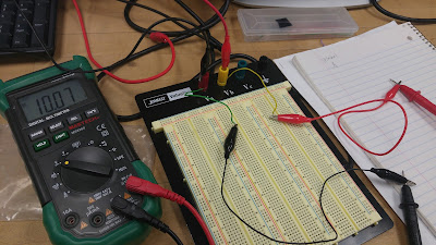
If the above images are inspected, one can see that the colors of the wires connecting to the Va and Vb terminals are reversed. As is the convention, the red wire here connects to the positive terminal of a voltage source and the black represents a negative terminal. It is important to note that these currents are generated separately using the A and B terminals of the Voltage source. This is shown in the following image.
Figure 6: Simultaneous 10 and -10 V reading setup
You can generate two separate voltages of -10 and 10 given that you preset values for A and B to 10 volts (on each) and set the output switch to independent. The only difference between a reading of positive and negative voltage is simply which way the voltage meter is connected to the circuit.
7. Apply 5V to a 100 Ω resistor and measure the current by using the DMM. Compare the reading with the current meter reading on the power supply. At what angle of the current knob makes the LED light on? If you keep on decreasing the current limit, what happens to the voltage and current? (Video)
Video 2: Example of Current Limit on a Voltage Source
8. Where is the fuse for the power supply? What is it for?
The fuse is on the rear panel of the power supply and functions as a safety measure that prevents excessive current from passing through by detaching, stopping the current.
9. Where is the fuse for the DMM? What is it for?
The fuse for the digital multimeter is in the bottom left corner of the front panel. its purpose is to protect other parts of the equipment from damage because high current would melt the fuse before it could ruin other components.
10. What is the difference between 2W and 4W resistor measurements?
The difference between the 2W and the 4W resistor measurements is that they accommodate different set-ups. The 2W setting can accommodate up to 100 Ω, while the 4W setting can accommodate up to 1000 Ω. The two different wires have resistance within, so with smaller resistances the 2W will add much less of an additional resistance due to the wire than that of the 4W.
11. How would you measure current that is around 10 A using DMM?
The fuse would have to be changed over to the 12 amp node on the front panel because the 10 amps would overload the lower node.


One aesthetic suggestion I have is to enlarge the pictures to fill up more white space on the blog and make them easier to see. I would look back at your answer to number 10 and add any detail that you can. I agree with what has already been written, but you should include some info as to why this is the case.
ReplyDeleteThanks for the idea of enlarging the pictures it makes the circuit much more visible. With the added information about the 2W and 4W their difference and function is more clearly defined.
DeleteOn #4 you uploaded the same photo to #5, supposed to be positive. A tip for future formatting, it would be visually pleasing to use bullet points and white space between the questions. Great job with the photo captions.
ReplyDeleteThank you for pointing out that the wrong picture was accidentally uploaded for the positive 30 Volts, i will definitely be more careful about that. That is also a good point about the use of white space; we will keep this in mind.
Delete